
Industry-leading Integration of PoE Technology and Renewable Power System
The BSP-360, Renewable Energy Industrial 802.3at PoE Managed Ethernet Switch, is designed for deploying a surveillance or wireless network and remotely monitoring and managing the IP-based devices. Based on its green technology, the BSP-360 can be charged by the inexhaustible and natural source of energy, such as solar, wind or hydroelectric power. This helps conserve energy and economically power remote IP cameras and wireless APs, especially in applications such as dams, forests, deserts, national parks, nature/animal protection areas and highways.
MPPT (Maximum Power Point Tracking) Charge Controller
The MPPT (Maximum Power Point Tracker) is an electronic DC to DC converter that optimizes the match between the PV solar panels and the battery bank or utility grid. They convert a higher voltage DC output from solar panels (and a few wind generators) to the lower voltage needed to charge the battery effectively.
Zero-Carbon and Stable Power Supply
The nickel-cadmium or lead-acid battery gets recharged by way of the BSP-360 where solar power is sourced. Thus, the BSP-360 will keep powering PD devices without the need of any cabling. Its zero-carbon feature is made possible as the energy the unit gets is renewable. Most importantly, the operation of outdoor wireless IP-based surveillance can be continued into the night as the battery is charged during the day.
Smart Battery Management
The BSP-360 features the following special power management functions:
- Current battery usage status by percentage
- Low voltage cut-off protection
Current Battery Usage Status
The administrator can remotely access the BSP-360 to know the power status of the battery and renewable energy, and the estimated time of power consumption.
Low Voltage Cut-Off Protection
If the remaining energy is too low to power the network, the system will automatically power off the device to make sure the system works normally, and an alert is then sent to the administrator at the same time.
Smart PoE PD Management
As it is the managed PoE switch for surveillance, wireless and VoIP networks, the BSP-360 features the following special PoE management functions:
- PD alive check
- PoE schedule
- PoE usage monitoring
- Scheduled power recycling
Intelligent Powered Device Alive Check
The BSP-360 can be configured to monitor connected PD (Powered Device) status in real time via ping action. Once the PD stops working and responding, the BSP-360 will resume the PoE port power and bring the PD back to work. It will greatly enhance the network reliability through the PoE port resetting the PDs power source and reducing administrator management burden.
Scheduled Power Recycling
The BSP-360 allows each of the connected PoE IP cameras or PoE wireless access points to reboot at a specific time each week. Therefore, it will reduce the chance of IP camera or AP crash resulting from buffer overflow.
PoE Schedule for Energy Saving
Under the trend of energy saving worldwide and contributing to environmental protection, the BSP-360 can effectively control the power supply besides its capability of giving high watts power. The PoE schedule function helps you to enable or disable PoE power feeding for each PoE port during specified time intervals and it is a powerful function to help SMBs or enterprises save power and budget. It also increases security by powering off PDs that should not be in use during non-business hours.
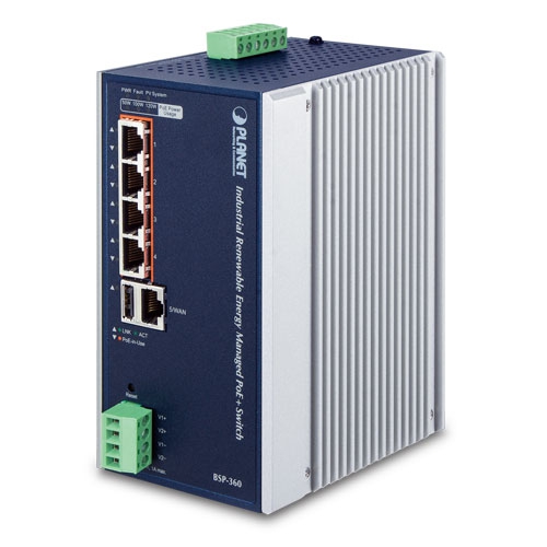
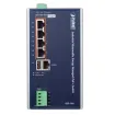
PoE Usage Monitoring and Intelligent LED Indicator for Real-time PoE Usage
Via the power usage chart in the web management interface, the BSP-360 enables the administrator to monitor the status of the power usage of the connected PDs in real time. Thus, it greatly enhances the management efficiency of the facilities. Moreover, the BSP-360 helps users to monitor the current status of PoE power usage easily and efficiently via its advanced LED indication. Called PoE Power Usage, the front panel of the BSP-360 has three LED indicators of different power usages.
User-friendly and Secure Management
For efficient management, the BSP-360 is equipped with web and SNMP management interfaces. With the built-in web-based management interface, the BSP-360 offers an easy-to-use, platform-independent management and configuration facility. By supporting the standard SNMP, the switch can be managed via any standard management software.
| Hardware Specifications | |
| Copper Ports | LAN: 5 10/100/1000Mbps auto MDI/MDI-X RJ45 port (Port 1 to Port 5, bridge mode) |
| WAN: 1 10/100/1000Mbps auto MDI/MDI-X RJ45 port (Port 5, gateway mode) | |
| PoE Injector Port | 4 ports with 802.3af/802.3at PoE injector function (Port 1 to Port 4) |
| USB | 1 USB Type A female for setting backup |
| Power Output | 4 PoE out 51VDC; max. 30 watts per PoE port |
| 2 DC out 24@ 1A maximum (four-pin terminal block) | |
| * The voltage of DC out is based on the battery. | |
| Switch Architecture | Store-and-Forward |
| Switch Fabric | 10Gbps/non-blocking |
| Switch Throughput@64 bytes | 5.95Mpps@64 bytes |
| MAC Address Table | 8K entries |
| Shared Data Buffer | 512Kbit |
| Flow Control | IEEE 802.3x pause frame for full duplex |
| Back pressure for half duplex | |
| Reset Button | < 5 sec: System reboot |
| > 5 sec: Factory default | |
| LED Indicators | 3 LEDs for System and Power: |
| Green: Power | |
| Red: Fault | |
| Green: System | |
| 4 LEDs for PoE Copper Ports (Port 1~Port 4): | |
| Green: LNK/ACT | |
| Orange: PoE-in-use | |
| 1 LED for 10/100/1000T Copper Port (Port 5): | |
| Green: LNK/ACT | |
| 3 LEDs for PoE Power Usage (W) | |
| Orange: 50, 100 and 120W | |
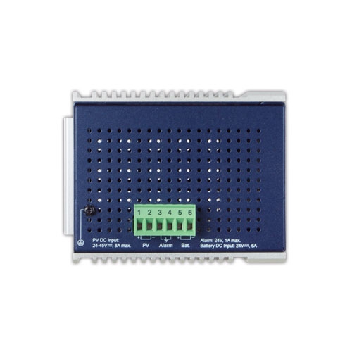
| Connector | Removable 6-pin terminal block |
| Pin 1/2 for PV panel; Pin 3/4 for alarm; Pin 5/6 for battery | |
| Alarm | 1 digital output (DO): |
| Level 0: -24V~2.1V (±0.1V) | |
| Level 1: 2.1V~24V (±0.1V) | |
| Open collector to 24V DC, 100mA max. | |
| Power Requirements | PV in: 24~45V DC |
| Battery in/out: 24V DC | |
| Power Consumption/ Dissipation | 5.04 watts, 17.1BTU (Standby without PoE function) |
| 6.96 watts, 23.7 BTU (Full loading without PoE function) | |
| 135.36 watts, 461.5 BTU (Full loading with PoE function) | |
| Dimensions (W x D x H) | 89 x 107 x 152 mm |
| Weight | 1026g |
| ESD Protection | 6KV DC |
| Enclosure | IP30 aluminum case |
| Installation | DIN-rail kit and wall-mount ear |
| Power over Ethernet | |
| PoE Standard | IEEE 802.3af/802.3at Power over Ethernet PSE |
| PoE Power Supply Type | End-span |
| PoE Power Output | Per port 51V DC, 275mA. Max. 15.4 watts (IEEE 802.3af) |
| Per port 51V DC, 535mA. Max. 30 watts (IEEE 802.3at) | |
| Power Pin Assignment | 1/2 (+), 3/6 (-) |
| PoE Power Budget | 120 watts (PoE consumption + DC out and depending on power input) |
| Max. Number of Class 2 PDs | 4 |
| Max. Number of Class 3 PDs | 4 |
| Max. Number of Class 4 PDs | 4 |
| Electrical Characteristics | |
| System Voltage Rating | 24V DC |
| Maximum Input Current | 6A |
| Max. Solar Array VOC | 60V DC |
| Max. Operating Voltage | 45V DC |
| Total Current Consumption | While operating -32mA |
| At idle -11mA | |
| High Temperature Shutdown | 100 degrees C (disconnect solar and loading) |
| 80 degrees C (reconnect solar and loading) | |
| Battery Charging Characteristics | |
| Charge Algorithm | The design presently uses perturb and observe algorithm for MPP tracking. |
| Maximum Output Current | 6A |
| Lead Acid Battery (Default Setting) | ± 60 mV/degrees Celsius for lead acid type batteries; charge cut-off @ 55 degrees C |
| (Temperature compensation baseline@ 25 degrees C) | |
| Float Charge Voltage | DC 27.2V (26.0~30.0V) |
| Absorption Charge Voltage | DC 29.2V (28.0~32.0V) |
| LVD (Low Voltage Disconnection) | DC 22.2V (21.0~25.0V) |
| LVR (Low Voltage Reconnection) | DC 22.4V (23.0~27.0V) |
| Router Features | |
| Internet Connection Type | Shares data and Internet access with users, supporting the following internet accesses: |
| PPPoE | |
| Dynamic IP | |
| Static IP | |
| PPTP | |
| L2TP | |
| Firewall | NAT firewall with SPI (Stateful Packet Inspection) |
| Built-in NAT server supporting Port Forwarding, and DMZ | |
| Built-in firewall with IP address/MAC address/Port/ URL filtering | |
| Supports ICMP-FLOOD, UDP-FLOOD, TCP-SYN-FLOOD filter, DoS protection | |
| Routing Protocol | Static/Dynamic (RIP1 and 2) routing |
| VPN Pass-through | PPTP, L2TP, IPSec, IPv6 |
| LAN | Built-in DHCP server supporting static IP address distribution |
| Supports UPnP, Dynamic DNS | |
| Supports IGMP Proxy | |
| Supports 802.1d STP (Spanning Tree) | |
| IP/MAC-based bandwidth control | |
| Management | |
| Management Interface | Setting up of system/management functions |
| Web firmware upgrade | |
| SNMP trap for alarm notification of events | |
| PoE Management | Power limit by consumption and allocation |
| PoE admin mode | |
| Per port power schedule | |
| Per port power enable/disable | |
| Power feeding priority | |
| Current per port usage and status | |
| Total power consumption | |
| PD alive check | |
| Scheduled power recycling | |
| Battery Management | Current battery usage status |
| Low voltage cut-off protection | |
| Standards Conformance | |
| Regulatory Compliance | FCC Part 15 Class A, CE |
| Standards Compliance | IEEE 802.3 10BASE-T Ethernet |
| IEEE 802.3u 100BASE-TX Fast Ethernet | |
| IEEE 802.3ab 1000BASE-T Gigabit Ethernet | |
| IEEE 802.3x Flow Control and Back Pressure | |
| IEEE 802.1D Spanning Tree Protocol | |
| IEEE 802.3af Power over Ethernet | |
| IEEE 802.3at Power over Ethernet Plus | |
| RFC 768: UDP | |
| RFC 791: IP | |
| RFC 2068 HTTP | |
| RFC 1157: SNMP v1 | |
| RFC 1902: SNMP v2c | |
| RFC 5424: Syslog | |
| Environment | |
| Operating | Temperature: -10 ~ 60 degrees C |
| Relative Humidity: 5 ~ 95% (non-condensing) | |
| Storage | Temperature: -10 ~ 70 degrees C |
| Relative Humidity: 5 ~ 95% (non-condensing) | |